Consider the planar truss with shape of power tower shown in the Figure. The points S and T are attached to the ground to constrain them in all directions. All cross members like CD and BE are made of cables, which means they are not capable of tolerating compression. Here we are willing to observe stress magnitudes in cables, CJ, HE, KN and IO. The results, then, will be compared with the ones given in reference [1]. The lengths of all members given in the Figure are in meter and their cross-sectional area is 0.15 m2. The material of members is, also, steel with Young’s Modulus of 210 Gpa.

Creating the model:
First of all, rename the model to power transmission truss. Click on icon ![]() (Create Part) and, in 2D planar space, create a deformable wire type part with name of PT-truss. For the reason mentioned in Example 1, we chose 28 as the approximate size. Now, go to Sketch module and clicking on icon
(Create Part) and, in 2D planar space, create a deformable wire type part with name of PT-truss. For the reason mentioned in Example 1, we chose 28 as the approximate size. Now, go to Sketch module and clicking on icon ![]() (Create Lines: Rectangle (4 Lines)) draw a rough approximation of Rectangle like what shown in Figure 2. Note that there is no need to set the corner on the origin because we are willing to use constraint tools to do this. Prior to this Example, we used to insert direct coordinates using Create Lines command to sketch parts. It seems clear that doing this makes the job complicate. In this Example, you will see by using of dimensional and geometrical constraints, creating sketch would be much easier.
(Create Lines: Rectangle (4 Lines)) draw a rough approximation of Rectangle like what shown in Figure 2. Note that there is no need to set the corner on the origin because we are willing to use constraint tools to do this. Prior to this Example, we used to insert direct coordinates using Create Lines command to sketch parts. It seems clear that doing this makes the job complicate. In this Example, you will see by using of dimensional and geometrical constraints, creating sketch would be much easier.

After this, click on icon ![]() (Create Lines: Connected) and start drawing zigzag lines including 6 members from left-bottom corner as displayed in Figure 3. Notice that each end point of lines must lay on the rectangle. If you do correctly, a small circle will appear on the endpoints.
(Create Lines: Connected) and start drawing zigzag lines including 6 members from left-bottom corner as displayed in Figure 3. Notice that each end point of lines must lay on the rectangle. If you do correctly, a small circle will appear on the endpoints.

To end the process of drawing lines click the Middle Button of mouse or press the Esc key. Next, sketch other lines which are specified in Figure 4 with black color. The numbers will help you to create these members in 3 steps [(1 to 6), (7 to 12 and 7), (13 to 18 and 13)]. Note that horizontally constrained lines will be symbolized by H. There may remain some horizontal lines without related constraint as circled by blue. We will make them constrained with required tools in future. Like before, the circles on lines end points, also, show that points lay on each other.

As we learnt through Figures 8 to 12 of Example 2, in order to avoid intersecting cross members, they must be created in Mesh module. Now, we are done with drawing the initial draft sketch and the next step is modifying it by constraints. Click on icon ![]() (Add Constraint). In emerged window, as specified in Figure 5, select the item Horizontal and after that, pick the lines that must be horizontal, but they do not have this constraint.
(Add Constraint). In emerged window, as specified in Figure 5, select the item Horizontal and after that, pick the lines that must be horizontal, but they do not have this constraint.

In order to applying equality on lines lengths select the item Equal length in Add Constraint window. Holding Shift key, click on lines A to H, which are shown in Figure 6, finally, click on Done button in prompt area. The sign / appears when this has done, showing the lines have constraints of equality.

While the Equal length tool is active, select the lines I, J, K, L which are displayed in Figure 7, simultaneously, then, press Done button.

Close Add Constraint window. To put dimensions on the structure, click on icon ![]() (Add Dimension) and select the points A and B. A red dimension line will appear. Click on a proper place where you want the dimension line to stay. In prompt area, you will be asked to insert the measure. According to Figure 1, insert the length of 2.21, here. Do the same for the all other points displayed in Figure 8.
(Add Dimension) and select the points A and B. A red dimension line will appear. Click on a proper place where you want the dimension line to stay. In prompt area, you will be asked to insert the measure. According to Figure 1, insert the length of 2.21, here. Do the same for the all other points displayed in Figure 8.

To ensure that the sketch has been entirely fixed, click on icon ![]() (Add Constraint) again. In opened window select item of Fixed, which is pointed out in Figure 9. This tool is used for fixing a point.
(Add Constraint) again. In opened window select item of Fixed, which is pointed out in Figure 9. This tool is used for fixing a point.

Considering Figure 8 select the point S, then, press Done button in prompt area. A triangle emerges next to the point selected which shows the point is fixed. Another thing is that the whole color of the sketch changes to green symbolizing all members are constrained entirely. This means drawing constrained sketch is done, so, press Done button to exit Sketch module. Figure 10 displays the truss after we exit the module.

Meshing the model:
To create the members remained enter Mesh module. First of all, we need to mesh the part we created in Sketch module. Like Figure 31 in Example 1 displayed, define only 1 element on each member. Clicking on icon ![]() (Mesh Part) and selecting Yes in prompt area, mesh the truss. To change the elements type click on icon
(Mesh Part) and selecting Yes in prompt area, mesh the truss. To change the elements type click on icon ![]() (Assign Element Type). Select all elements by dragging then press Done. In opened window, then, select Truss item as the element type of chosen elements. In this step, we can create elements of cross members remained as you learnt through Figures 8 to 11 in Example 2. To create the first member, as seen in Figure 11, select nodes T and Q, one after another, then, press OK in prompt area. Do the same for nodes, Q and O, O and I, I and J, J and C, and finally, C and D. Remember in each step click on OK button to create the relevant elements.
(Assign Element Type). Select all elements by dragging then press Done. In opened window, then, select Truss item as the element type of chosen elements. In this step, we can create elements of cross members remained as you learnt through Figures 8 to 11 in Example 2. To create the first member, as seen in Figure 11, select nodes T and Q, one after another, then, press OK in prompt area. Do the same for nodes, Q and O, O and I, I and J, J and C, and finally, C and D. Remember in each step click on OK button to create the relevant elements.

After all, assign Truss element type to the meshes just created. To do this, click on icon ![]() (Assign Element Type) again but this time select orphan mesh as the region of assigning element types as shown in Figure 12.
(Assign Element Type) again but this time select orphan mesh as the region of assigning element types as shown in Figure 12.
")
Select whole of the structure, however, only the members that were created by Edit Mesh tool will be picked. Press OK in prompt area, then, in Element Type window choose the item Truss as the type of elements.
Material property definition:
As we mentioned above, all members are made from steel, however the steel cables cannot bear compression. Considering this, Enter Property module and create a material with name of Steel-bar. As Figure 13 shows, insert 210 Gpa for the modulus of elasticity and 0 for Poisson’s ratio.

By clicking on OK button, the material will be defined in the model. This material will be assigned to the bars. To determine the material of cables, like what you see in Figure 14, create another material named Steel-cable, and insert the same young’s module and Poisson’s ratio, but enable the item No compression as well. Obviously, by doing this, the related elements will not tolerate compression.

Create Section as displayed in Figure 15, by clicking on icon ![]() (Create Section). Name it Section-bar and select Truss as its type. In addition, consider its cross sectional area 0.15 m2 and choose its material the Steel-bar option.
(Create Section). Name it Section-bar and select Truss as its type. In addition, consider its cross sectional area 0.15 m2 and choose its material the Steel-bar option.

Make another section with name of Section-cable considering the conditions seen in Figure 16.

In this step, assign the sections on related members (bars or cables). To do this, click on icon ![]() (Assign Section) and for the bar members, select Geometry in prompt area. To select the bars, drag the mouse and choose all members. Selected members will be shown in red. Holding Ctrl key, click on cross members specified in Figure 17 by black color, one by one. This makes them deselect. After all, only bars must be remained red.
(Assign Section) and for the bar members, select Geometry in prompt area. To select the bars, drag the mouse and choose all members. Selected members will be shown in red. Holding Ctrl key, click on cross members specified in Figure 17 by black color, one by one. This makes them deselect. After all, only bars must be remained red.

Finally, press Done in prompt area and select the section pointed out in Figure 18, then, OK.

In order to assign sections to the cables, first, let’s hide the bars in viewport to ease selecting bars. To do this, click on icon of shown in Figure 19.

In opened window, while Section-bar is selected, press Edit button. By this, the bar members activates. Now, you can hide them by Remove Selected tool which is circled in Figure 20.

Now, we only have cables in viewport which is much easier to select. Firstly, close all opened window, then, click on icon ![]() (Assign Section) and assign Section-cable to the cables in Geometry region. Next, do the same for the elements in Mesh region. Figure 21 shows selecting Section-bar for both regions.
(Assign Section) and assign Section-cable to the cables in Geometry region. Next, do the same for the elements in Mesh region. Figure 21 shows selecting Section-bar for both regions.

The action of section assignment is done, so, let’s bring back the bars to the viewport and show all members of the tower. To do this, click on Replace All icon in Display Group tools box, displayed in Figure 22.

Inserting the truss in Assembly module:
Enter Assembly module and bring the part created into assembly environment. At this step, save the model in a folder with name of 2D truss-cable.
Define the static analysis:
Enter the Step module, and create a Static, General step with its default options.
Defining boundary conditions:
Enter Load module. In order to constrain the support points which are specified with S and T in Figure 23, click on icon ![]() (Create Boundary Condition).
(Create Boundary Condition).

In opened window, select the items displayed in Figure 24 and Continue.

Choose Geometry in prompt area, and holding Shift key, select both points and Done. In Edit Boundary Condition enable U1 and U2 and finally, press OK to keep them from moving in X and Y directions.
Applying loads:
Figure 1 shows there is an angle of 20o between forces and the vertical direction. In order to define these forces, we can take following actions:
1- We can simply project their vectors on X and Y directions as their components are calculated below:
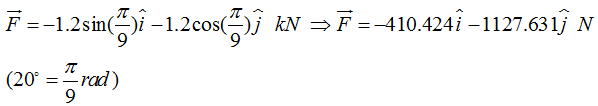
2- We can define them in local coordinate systems which is rotated 20o.
In this Example we choose the second method and define a local coordinate system with rotation of 20o. To do this, we require 3 points that will be created in following steps.
Enter Part module and in model tree (Figure 25) click on ![]() signs next to Parts, until you find Section Sketch. Right click on it and select Edit to enter Sketch module again.
signs next to Parts, until you find Section Sketch. Right click on it and select Edit to enter Sketch module again.

In an empty area, using Create Lines tool, draw 2 new lines like what seen in Figure 26. Put an angle of 20o between them. Notice V sign meaning vertical beside the vertical line. In case this sign did not appear, which means the line may not be vertical, using Add Constraint tool and Vertical item, you can make the line constrained.

Do not forget the lines must not intersect any part of the truss; otherwise, there occur problems in sections, meshes, etc. Press Done button in prompt area and exit Sketch module. A warning message appears telling that you must regenerate the feature to include the new lines drawn, into the part. Regarding this, select Feature in menu bar, then, Regenerate (See Figure 27).

This makes the lines, just drawn, appear in viewport. Now, to define local coordinate system, enter Load module. After that, select Tools, then, Datum from the menu bar. As displayed in Figure 28, select the items specified. These items create a local coordinate system based on 3 points.

By selecting the items mentioned, a window titled Create Datum CSYS opens. Configure the window same as Figure 29 and Continue.

In prompt area, you will be asked to select the origin of coordinates, firstly. So, choose the point number 1 in Figure 30. After that, select the second point which will be considered as a point on X axis. Obviously, this point determines the X axis and by clicking on it, a red coordinate system emerges on the point 1 which is what we want. So, press Create Datum and finish the process. At the end you need to close opened windows, Create Datum CSYS and Create Datum.

Like always for applying loads, which are 1200 N here, click on icon ![]() (Create Load). Figure 31 shows selecting Concentrated force to create it in Step-1. Continue to the next stage.
(Create Load). Figure 31 shows selecting Concentrated force to create it in Step-1. Continue to the next stage.

Select Geometry button in prompt area and holding Shift key, select 6 points numbered in Figure 32 and, finally, press Done.

In Edit Load window, first, considering Figure 33, click on icon ![]() (Edit) to choose our local coordinate system that we create in previous step.
(Edit) to choose our local coordinate system that we create in previous step.

You can click on the CSYS directly in viewport or select it from the list of datum. Use the second way and press the button of Datum CSYS List, pointed out in Figure 34.

Among items in opened window, seen in Figure 35, choose the local system we named cys-20degree and press OK. This brings you back to the Edit Load window to insert magnitude of the force.

As you may guess, in Edit Load window, CF1 and CF2 are related to the forces along X and Y directions of either Global or Local coordinate systems, respectively. Insert the magnitude of 1200 in edit box of CF1 as shown in Figure 36. Note that you can reverse the direction of force by negative numbers, however in this Example, the X axis of local coordinate and the forces are in the same orientation.

As you press OK button, the forces will appear in viewport displayed in Figure 37.

Now, the model is ready to get analyzed.
Analyzing the problem:
Enter Job module and create a job with name of cable-truss, then, submit it to the solver. A warning, shown in Figure 38, comes up alerting that the PT-truss-1 is not meshed completely and unmeshed regions will be excluded from your analysis. This is because of existing those two lines we drew to create local coordinate system which are not actually included in the structure. So, press Yes to neglect them in the simulation.

When the job finished, click on Monitor in Job Manager window to check if there is any Warning, although, no message exists. Next, press Results to go to Visualization module in order to assessing the results. Click on icon ![]() (Plot Contours on Deformed Shape) that gives you deformed shape of the power transmission tower. Considering Figure 1 and using the methods you have learned in prior Examples, obtain the magnitudes of stresses in members of CJ, HE, KN and IO. The forces in these members are calculated by multiplying the stress by members cross sectional area (0.15 m2). The results earned from Abaqus/CAE and given in reference [1] are presented in table 1.
(Plot Contours on Deformed Shape) that gives you deformed shape of the power transmission tower. Considering Figure 1 and using the methods you have learned in prior Examples, obtain the magnitudes of stresses in members of CJ, HE, KN and IO. The forces in these members are calculated by multiplying the stress by members cross sectional area (0.15 m2). The results earned from Abaqus/CAE and given in reference [1] are presented in table 1.
Table 1: Results obtained from Abaqus/CAE and Ref [1] 
Exercise:
Consider the truss displayed in Figure 41. In this structure, cables are used to make the members BG, CF, CH and DG. In addition, the support joint G is constrained in vertical orientation but the F is fixed in both translational directions. The lengths are in foot and the members are made of steel with Young’s modulus of 30×106 psi. Moreover, their cross sectional area is 10 in2. You are asked to find forces in all cables. Take notice that first, convert the lengths to inch.

Answers:
Table 2: Results obtained from Abaqus/CAE and Ref [1] 
Reference:
[1] Beer, F. P., and Johnston, E. R., Jr., “Vector Mechanics for Engineers: Statics and Dynamics,” McGraw-Hill Book Co., Inc. New York, 2012, p. 312.
Be the First to Comment!